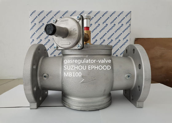
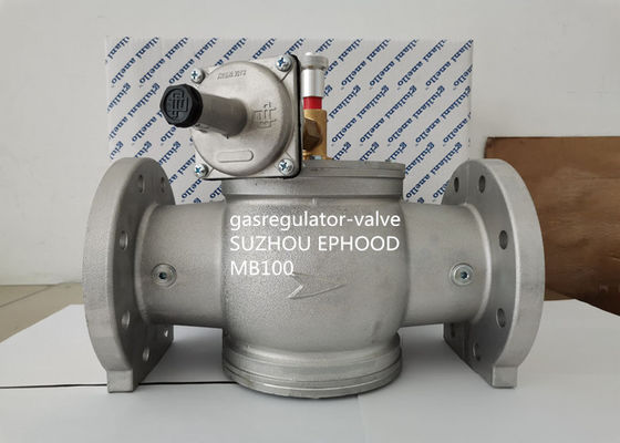
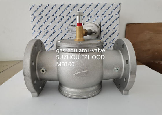
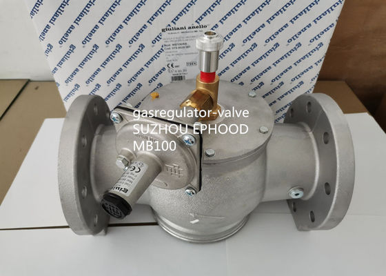
Italy giuliani anello Made Aluminium Pressure Regulator With Built-in Filter
MB100-6B
Application
Fuel: all three families of gas (city gas, methane, LPG); non aggressive gases.
Technical Specifications
Connection: threaded UNI EN 10226-1; flanged PN16 EN1092-4
Maximum inlet pressure: 1 bar (MB); 6 bar (MB/6B)
Ambient temperature: -10°C to 60°C
Response pressure: blue spring: 30 to 120 mbar;neutral spring: 80 to 550 mbar
Max surface temperature: 60°C
Material: aluminium valve's body and cover; stainless steel springs and control piston; NBR rubber basket and O-ring;other part are of brass, aluminium and galvanised steel.
General information
The maximum pressure slam shut off valves in the MB and MB/6B series are safety devices kept open under normal work conditions thanks to an automatic mechanism triggered upon
manually rearming. If the shut off plenum detects an inlet pressure greater than the alibration value, it releases the closure device which stops the gas flow.
Rearming
These valves are rearmed solely by hand in order to be able to check and clear the causes of the emergency. To assist the rearming, all flanged models are equipped with a dual gate pin, which prevents having to construct by-passes on the piping between valve upstream and downstream. To rearm the valves with dual gate pin follow the instructions enclosed inside the pack, whereas for the threaded series, which has only one gate
pin, simply pull the aluminium knob above the valve sleeve.
Calibration
1. Check that all the utilities are off.
2. Slowly open the on/off valve upstream of the system.
3. Increase the shut off pressure by turning the appropriate adjusting screw.
4. Open the valve by following the rearming procedure; if the valve closes again, increase the shut off pressure again.
5. Increase the regulator outlet pressure until the set shut off value. If while increasing the regulator the pressure, the shut off valve is triggered, increase the shut off pressure until the valve is rearmed.
6. Slowly decrease the shut off pressure until the valve is triggered.
7. Restore the initial regulator outlet pressure.
8. Screw on the plastic safety caps on the screws that adjust the regulator and the shut off valve.
Maintenance
The shut off valves do not require any special maintenance. In the event of a fault, run a general overhaul and relative test on site. Periodically check the working efficiency of the entire safety system by increasing the regulator pressure until the shut off valve is triggered. If the valve must be disassembled for any reason, make sure there is no pressure in the circuit.
|
Model
|
Part Number
|
Description
|
End
|
| FGDR32 |
009.0223.101 |
With neutral spring 10-25 mbar |
1-1/4" |
| FGDR32 |
009.0223.102 |
With green spring 5-15 mbar |
1-1/4" |
| FGDR32 |
009.0223.103 |
With violet spring 20-70 mbar |
1-1/4" |
| FGDR32 |
009.0223.104 |
With brown spring 65-130 mbar |
1-1/4" |
| FGDR32 |
009.0223.106 |
With white spring 120-250 mbar |
1-1/4" |
| FGDR32 |
009.0223.107 |
With black spring 240-350 mbar |
1-1/4" |
Installation
The maximum pressure slam shut off valves MB - MB/6B conform to Directive 2014/34/UE (ATEX) in group II category 2G and in group II, category 2D; as such they are suitable for
installation in zones 1 and 21 and, even more so, in zones 2 and 22 as classified in enclosure I of Directive 99/92/EC.
The shut off valves described here are not suitable for use in zones 0 and 20 as defined in Directive 99/92/EC. To determine the qualification and extension of the hazardous zones, see standard EN 60079-10. If installed and maintained as per the conditions and instructions given in the enclosed technical manual, the shut off valve is not a source of specific danger.
In particular, under normal operating conditions, the device does not emit inflammable substances such as to generate an explosive atmosphere. The shut off plenum has a work membrane and a safety membrane; if the work membrane breaks, the safety membrane guarantees gas emission with flow rate no higher than 30 dm3/h.
A continuous explosive atmosphere able to generate a hazardous zone 0 is emitted solely in the event both membranes break simultaneously. In the event the valve is installed in an
unmanned or poorly aired location, all the necessary precautions should be taken to prevent the valve from being the cause of a zone 0. For example, the shut off plenum breather may be routed outside via a copper pipe connected to the threaded hole G1/8" by removing the dustproof brass cap.
The assembly position is indifferent; on horizontal piping, do not position the valve rearming knob facing down. The following guidelines should be followed: do not lever on the sleeve when assembling the valve; ensure that the piping is well aligned and that there are no obstructions or dirt inside; observe the flow direction as shown by the arrow printed on the valve body; check that all pressure, voltage, temperature etc. parameters are complied with; do not install the valve in contact with plastered walls; do not hinder or in any way obstruct the stroke of the rearming knob, as closure may not be guaranteed; fit a suitable gas upstream of the valve. The shut off valve should be installed upstream of the pressure regulator. The impulse outlet (threaded hole G1/8") on the plenum should be connected via copper pipe, with diameter no less than 4 mm, downstream of the regulator at a distance from the regulator of 5 times the diameter of the pipe.


 Your message must be between 20-3,000 characters!
 Please check your E-mail!
  Your message must be between 20-3,000 characters!
 Please check your E-mail!


