Send Message

Suzhou Ephood Automation Equipment Co., Ltd.


Gas Regulator,Pressure Transmitter,SUFA Water Valve

Home ProductsFisher Gas Regulator

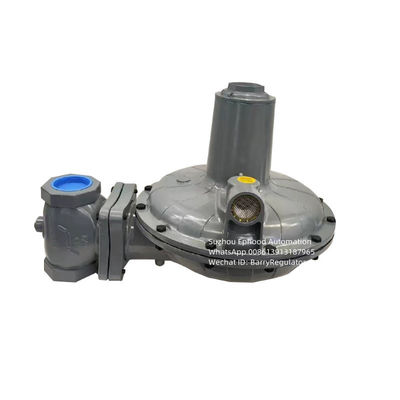
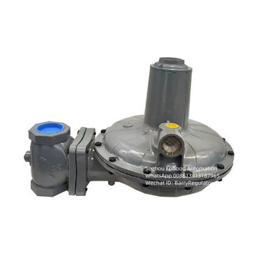
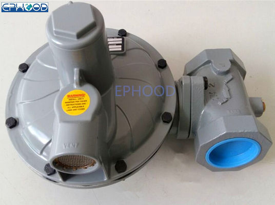
Fisher CS400 2 Inch End Connection Fisher Regulator Valve CS400IN8EC8 Use On Gas Boiler

Fisher CS400 2 Inch End Connection Fisher Regulator Valve CS400IN8EC8 Use On Gas Boiler

  • Fisher CS400 2 Inch End Connection Fisher Regulator Valve CS400IN8EC8 Use On Gas Boiler
  • Fisher CS400 2 Inch End Connection Fisher Regulator Valve CS400IN8EC8 Use On Gas Boiler
Fisher CS400 2 Inch End Connection Fisher Regulator Valve CS400IN8EC8 Use On Gas Boiler
Product Details:
Place of Origin: Made In China
Brand Name: Fisher
Model Number: CS400IN8EC8
Payment & Shipping Terms:
Minimum Order Quantity: Negotiation
Price: Negotiation
Packaging Details: 1set packed in one carton,5.5kg each one.
Delivery Time: 3 work-days
Payment Terms: T/T, Western Union, MoneyGram
Supply Ability: 100sets Every Month
Contact Now
Detailed Product Description
Name: Fisher CS400 Pressure Gas Regulator End Connetion: 2" NPT(DN50)
Inlet Pressure: 20psi/1.4bar Outlet Pressure Range: 10-14"W.C(25-35mbar)
Pressure Registration: Internal Flow Rate: 120m³/h
Orifice Size: 3/4" Overpressure Protection Module: Without
High Light:

fisher flow control valve

,

fisher differential pressure regulator

Fisher Brand Pressure Gas Regulator Model CS400IN8EC8
Fisher CS400 Series direct-operated, spring-loaded regulators provide pressure-reducing applications for

commercial and light industrial installations. 
Features
Wide Variety of Body Sizes and End Connections
Fixed Factor / Pressure Factor Measurement (PFM) Accuracy Capabilities
Field Convertible from Internal Sensing to External Sensing for Wide-Open Monitor Construction
Available in Gray Cast Iron, Ductile Iron, and Steel Body Materials
Only Standard Tools Required for Pressure Adjustment and Orifice Removal
Easy to Maintain
 
Specifications
Body Material, End Connection Size and Styles, Pressure Rating
Ductile Iron, 1-1/2”NPT* 1-1/2”NPT and 2”NPT*2”NPT
175psi/12.1bar
Maximum Inlet Pressure
175 psig / 12.1 bar ,See Table 2
Outlet Pressure Ranges
Regulator: See Table 5
Pressure Registration
Internal or External
Approximate Weight:With Threaded Body
Type CS400: 5 kg
PED Conformity Statement and Information
The CS400 Product Series is in conformity with the Pressure Equipment Directive PED 97/23/EC.The exception to this previous statement is the Type CS403 which is not yet certified to conform
with the PED Directive.
Pressure regulator does not require any supplementary upstream safety accessory for protection against overpressure compared with its design pressure PS, when upstream reducing station is sized for a max downstream incidental MIPd <= 1.1 PS.
Principle of Operation
Type CS400 Base Regulator Operation
Refer to Figure of Fisher CS400 Series When downstream demand decreases, the pressure under the diaphragm increases. This pressure overcomes the regulator setting (which is set by the regulator control spring). Through the action of the pusher post assembly, lever, and valve stem, the valve disk moves closer to the orifice and reduces gas flow. If demand downstream increases, pressure under the diaphragm decreases. Spring force pushes the pusher post assembly downward, the valve disk moves away from the orifice, and the gas flow increases downstream as the regulator opens in response to the decreased pressure underneath the diaphragm.
The Type CS400IR regulator includes an internal relief valve for overpressure protection. If the downstream pressure exceeds the regulator setting by 7 to 28 inches w.c. / 17 to 69 mbar (depending on the main spring used), the relief valve opens and excess gas is vented through the stabilizer vent in the upper spring case.
General Installation Instructions
Before installing the regulator,

  • Check for damage, which might have occurred during shipment.
  • Check for and remove any dirt or foreign material, which may have accumulated in the regulator body.
  • Blow out any debris, dirt or copper sulfate in the copper tubing and the pipeline.
  • Apply pipe compound to the male threads of the pipe before installing the regulator.
  • Make sure gas flow through the regulator is in the same direction as the arrow on the body. “Inlet” and “Outlet” connections are clearly marked.
  • When designing a pressure reducing station using a CS400 Series regulator, make an analysis if it is necessary to take into account the effects of wind, snow, and temperature to avoid unnecessary load and movement to the flanges of the equipment.

Installation Location
The installed regulator should be adequately protected from vehicular traffic and damage from other external sources.
 
Table 5. Outlet Pressure Ranges

Type OUTLET PRESSURE RANGE SPRING SPRING WIRE DIAMETER SPRING FREE LENGTH
COLOR Inch mm Inch mm
CS400 3.5 to 5" w.c. / 9 to 12 mbar Red 0.098 2.49 4.18 106
4.5 to 6.5" w.c. / 11 to 16 mbar Purple 0.080 2.03 4.32 110
6 to 8" w.c. / 15 to 20 mbar Gold 0.108 2.74 4.18 106
7.5 to 11" w.c. / 19 to 27 mbar Blue 0.110 2.79 4.40 112
10 to 14" w.c. / 25 to 35 mbar Unpainted 0.110 2.79 4.40 112
12 to 19" w.c. / 30 to 47 mbar Green 0.112 2.85 4.70 119
18" w.c.to 1psig / 45 to 69 mbar Orange 0.120 3.05 4.94 125
1 to 2 psig / 69 to 138 mbar Black 0.140 3.56 4.66 118
2 to 5.5 psig/ 138 to 380 mbar Yellow 0.172 4.37 4.42 112

 
Fisher CS400 2 Inch End Connection Fisher Regulator Valve CS400IN8EC8 Use On Gas Boiler 0
Fisher CS400 2 Inch End Connection Fisher Regulator Valve CS400IN8EC8 Use On Gas Boiler 1
Fisher CS400 2 Inch End Connection Fisher Regulator Valve CS400IN8EC8 Use On Gas Boiler 2
 Fisher CS400 2 Inch End Connection Fisher Regulator Valve CS400IN8EC8 Use On Gas Boiler 3
 

Contact Details
Suzhou Ephood Automation Equipment Co., Ltd.

Contact Person: Mr. Barry Wang

Tel: +86-1391-318-7965

Fax: 86-512-66079692

Send your inquiry directly to us (0 / 3000)

Other Products