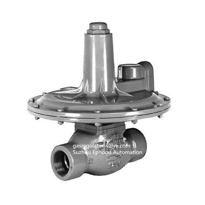
Fisher 133 Series Direct Operated Pressure Reducing Regulator
Fisher 133 Series direct-operated regulators are ideal for industrial and commercial applications supplying gas to furnaces, burners, and other appliances. A balancing system enables the regulator to control gas pressure accurately for maximum combustion efficiency despite varying inlet pressures.
Features
• Wide Pressure Range Capability with Single Regulator—Type 133H may also use Type 133L springs, allowing pressure settings to be varied between 2 inches w.c. and 10 psig / 5 mbar and 0.69 bar by changing springs.
• Types 133L, 133H, and 133HP Suitable for Monitoring Applications—O-ring stem seal on Types 133L, 133H, and 133HP isolates body pressure from controlled pressure. • Excellent Shock Characteristics and Fast Speed of Response—Due to two-way stabilizer vent valve, which vents the spring case more rapidly than conventional vents, lag in diaphragm and valve disk movement is minimized.
• Bubble-Tight Shutoff—Single-port construction, large diaphragm area, and light-rate springs along with disk material and seat design provide low lock-up pressures.
• Spring and Diaphragm Effects Minimized— Boosting system provides excellent performance over a wide range of fl ow conditions.
• No Seat-to-Seat Adjustment Required—Balanced single-port design eliminates necessity for seat-to- seat adjustments to achieve bubble-tight shutoff.
• Easy Access to Trim Parts—Valve seat, disk, and cage easily removed with body remaining in line and without disassembly of actuator portion; orifi ce is not threaded in.
• Reusable Pressure Seals—O-rings used for pressure seals, unlike gaskets, are not ordinarily damaged by disassembling the regulator.
• Resistance to Piping Stresses—Steel constructions are available to help resist pipe stresses.
Specifications of Fisher 133L
Available Constructions
Type 133H: Direct-operated regulator for inlet pressures to 60 psig / 4.1 bar and outlet pressures from 1.5 to 10 psig / 0.10 to 0.69 bar, three ranges.
Type 133HP: Direct-operated regulator for inlet pressures to 150 psig / 10.3 bar and outlet pressures from 2 to 60 psig / 0.14 to 4.1 bar, seven ranges.
Type 133L: Direct-operated regulator for inlet pressures to 60 psig / 4.1 bar and outlet pressures from 2 inches w.c. to 2 psig / 5 mbar to 0.14 bar, six ranges.
Type 133Z Zero Governor: Direct-operated regulator for inlet pressures to 20 psig / 1.4 bar and outlet pressures from -1 to 4-inches w.c. / -2.5 to 10 mbar, two ranges.
Body Size and End Connection Styles
| BODY SIZES |
BODY MATERIAL |
| NPT |
DN |
Cast Iron Body |
WCC Steel Body |
| 2" |
50 |
NPT or CL125 FF Flanged |
NPT or CL150 RF Flanged |
Maximum Inlet Pressures(1)
See Table 2
Outlet Pressure Ranges(1)
See Table 1
Maximum Outlet Pressures(1)
See Table 2
Pressure Registration
External; downstream control line is required
Control Line Connection
Types 133H, 133L, and 133Z: 3/4 NPT internal connection will be positioned directly over body outlet (standard position) or 90° right or left of standard position if specified.
Type 133HP: 1/4 NPT Internal connection positioned directly over body outlet.
Vent Connection
Types 133H, 133L, and 133Z: 1 NPT internal with screen; standard position is in line with control line connection directly over body outlet. Vent will always be positioned over the control line connection.
Type 133HP: 1/2 NPT internal connection positioned directly over body inlet with a Fisher Type Y602-7 vent assembly.
Construction Materials
Body: Cast iron or WCC Steel
Orifice and Cage: Aluminum
Valve Disk: Aluminum/Neoprene (CR) or Aluminum/Fluorocarbon (FKM)(3)
O-rings: Nitrile (NBR) or Fluorocarbon (FKM)(3)
Diaphragms: Nitrile (NBR)/Nylon (PA) (Neoprene (CR) in actuator)
or Fluorocarbon (FKM)(3)/Polymer Thermoplastic
Guide Bushing: Nylon (PA)
Stem and Stem Sleeve: Stainless steel
Diaphragm Plate: Steel
Balancing Diaphragm Plate: Plated steel
Spring Case and Closing Cap:
Type 133HP: Cast Iron
Types 133H, 133L, and 133Z: Aluminum
Lower Casing:
Types 133H, 133L, and 133Z: Aluminum
Type 133HP: Steel
Adjusting Screw:
Types 133H and 133Z: Brass
Type 133L: Aluminum
Type 133HP: Steel
Optional Restriction Collar: Aluminum
Approximate Shipping Weight
Types 133H, 133L, and 133Z NPT End Connections: 35 pounds / 16 kg
Types 133H, 133L, and 133Z Flanged End Connections: 40 pounds / 18 kg
Type 133HP NPT End Connections:
56.5 pounds / 26 kg
Type 133HP Flanged End Connections:
62.5 pounds / 28 kg
Table 1. Fisher 133 Series Outlet Pressure Ranges
| TYPE |
OUTLET PRESSURE RANGE |
CONTROL SPRINGS |
| Psi |
Bar |
Color Code |
Free Length |
Wire Diameter |
| Inch |
mm |
Inch |
mm |
| 133H |
1.5 to 3
2 to 5
5 to 10 |
0.10 to 0.21
0.14 to 0.34
0.34 to 0.69 |
Orange
Yellow
Blue |
6.91
6.47
6.19 |
176
164
157 |
0.250
0.283
0.375 |
6.35
7.19
9.53 |
| 133HP |
2 to 5
4.5 to 10
6 to 20
16 to 30
26 to 40
36 to 50
45 to 60 |
0.14 to 0.34
0.31 to 0.69
0.41 to 1.4
1.1 to 2.1
1.8 to 2.8
2.5 to 3.4
3.1 to 4.1 |
Yellow
Orange
Silver
Red
Blue
Green
White |
8.5
8.5
8.25
8.25
8.25
8.25
8.25 |
216
216
210
210
210
210
210 |
0.282
0.343
0.375
0.438
0.500
0.500
0.531 |
7.16
8.71
9.52
11.1
12.7
12.7
13.5 |
| 133L and 133H |
2” to 4” w.c.
3.5” to 6” w.c.
5” to 9” w.c.
8.5” to 18” w.c.
14” to 28” w.c.
0.75 to 2 |
5 to 10 mbar
9 to 15 mbar
12 to 22 mbar
21 to 45 mbar
35 to 70 mbar
0.05 to 0.14 |
Brown
Red
Black
White
Green
Blue |
6.13
7.53
7.88
7.5
7.25
7.09 |
156
191
200
191
184
180 |
0.109
0.112
0.130
0.156
0.182
0.225 |
2.77
2.84
3.30
3.96
4.62
5.72 |
Introduction Description
The 133 Series direct-operated gas regulators, shown in Figure 1 are primarily designed for industrial and commercial applications supplying gas to furnaces, burners, and other appliances. The 133 Series balancing system enables the regulator to provide accurate control of gas pressure for maximum combustion efficiency despite varying inlet pressure conditions. The single port construction provides bubble-tight shutoff. An external downstream control line is required for the operation of the regulator. Refer to Table 1 for outlet pressure ranges of each type. 133 Series regulators are available in a 2 inch / DN 50 body size with either NPT or flanged end connections. An optional restriction collar (Figure 2) can be installed if wide-open capacity is too high for applications using a relief valve as overpressure protection. The collar reduces wide-open capacity to 25%, 40%, or 60% of standard wide-open capacity.
Principle of Operation
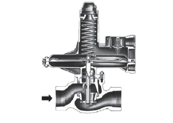
Refer to the operational schematics in Figure 4. In the 133 Series, downstream pressure is registered under the diaphragm via the external control line and is used as the operating medium. Increased demand lowers the downstream pressure and allows the spring to move the diaphragm and stem assembly down, opening the valve disk and supplying more gas to the downstream system. Decreased demand increases the downstream pressure and moves the diaphragm and stem assembly up, closing the valve disk and decreasing the gas supply to the downstream system.
Boosting System
The 133 Series incorporates a balancing diaphragm and a boosting system. When the regulator is locked up, inlet pressure is registered on the top of the valve disk and on the bottom of the balancing diaphragm through registration holes in the top of the cage. Also, downstream pressure is registered on the bottom of the valve disk and on the top of the balancing diaphragm through a passage formed by grooves in the registration disk and an annular space between the stem and stem sleeve. When the valve disk is open, gas flows from the inlet over the edge of the valve disk to the outlet. Under the valve disk near the registration disk, there is little gas flow. The gas pressure near the registration disk is higher than it is in the flow path where gas velocity tends to lower the pressure. The higher pressure near the disk is registered on the top of the balancing diaphragm through the registration disk and the annular space between the stem and stem sleeve. This pressure registered on the top of the balancing diaphragm aids downward disk travel and compensates for spring and diaphragm effect. This improves regulator range ability and performance. Two-Way Stabilizer Vent Valve on Types 133H, 133L, and 133Z When the regulator responds to an increase in downstream pressure, the diaphragm moves upward. As the diaphragm rises, movement of air forces the lower vent stabilizer upward, carrying the upper stabilizer with it (see Figure 5). This allows the air above the diaphragm to vent to atmosphere rapidly enough to minimize lag in diaphragm movement. As the diaphragm falls, air rushes in the vent to fill the partial vacuum created, forcing the upper vent stabilizer against the orifice plate. Air flowing through the webs of the upper stabilizer opens the lower stabilizer (see Figure 5). With the regulator at steady-state conditions, both stabilizers are closed and only a small hole is open to help stabilize normal operation.
Overpressure Protection
As is the case with most regulators, the 133 Series regulators have outlet pressure ratings that are lower than the inlet pressure ratings. Some type of Overpressure Protection is needed if the actual inlet pressure ever exceeds the outlet pressure rating. Maximum inlet and outlet pressures for the 133 Series are given in Table 2. All models must be protected against inlet pressure above the maximum emergency inlet pressure (refer to Table 2). Outlet pressure more than 3 psig / 0.21 bar for Types 133H, 133L, and 133Z, or 40 psig / 2.8 bar for Type 133HP over the outlet pressure setting of the regulator may damage internal parts such as the diaphragm plate and valve disk. Regulator operation below these emergency pressure limitations does not preclude the possibility of damage.


 Your message must be between 20-3,000 characters!
 English